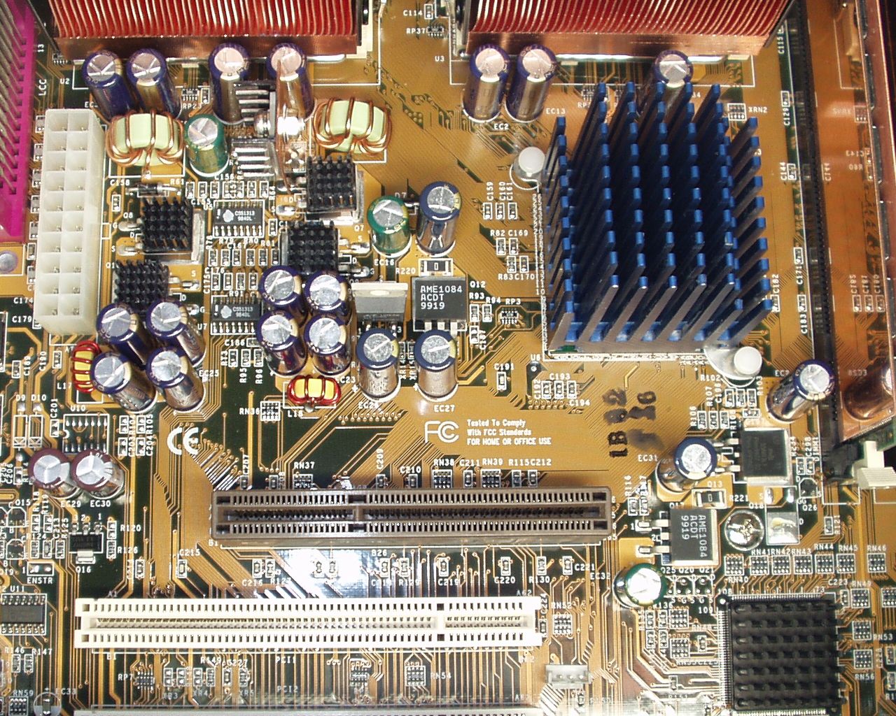
The mother board of PC ABIT's BP6, that had been used for the file server at home,
revived for families. With this given opportunity of maintenance, I tried to make modifications over it as hobby.
Some unstable factors resulting from the mother board when overclocking the 'Celeron 366'
in dual operation are resolved and came to carry out stable operation at 100MHz FSB.
[Jul/12/2004]
ABIT's BP6 is the mother board which was put on the market in 1999, which won reputation by saying that dual CPU operation can be performed with cheap Celeron processor.
It is popular to the extent that there is a website called bp6.com even now.
Although this is an interesting mother board, parts are stingy fairly and there is a problem for stable operation.
The main problems are the inadequate decouplings by the shortage of a performance of a low drop out voltage regulator.
So called EC10 problem*1 is also equivalent to this.
There is a part where series voltage regulator AME1084 and AME1085 are used in BP6,
and if these regulators have low ESR of a decoupling capacitor at the output, they will cause oscillation.
Even if it does not go to an oscillation, output voltage sharply changed by change of load current.
That is, in order to improve a load regulation, even if he wants to attach a large capacitance high performance
capacitor, it cannot be attached. What is necessary is just to improve these parts.
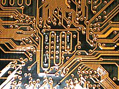
[fig.1 BP6 Voltage regulators]
The modification parts are as follows in the large order of the effects.
1) Vtt relating circuit
2) Vmem/Vio relating circuit
3) V2.5 relating circuit
4) Vcore relating circuit
5) Fan control output
Vtt relating circuit
Q6:AME1085CD It exchanged to LT1585CT of Linear technology (or LMS1585A of National semiconductor) with small heat sink attached.
This voltage regulator is pin compatible with 1085 but offer lower dropout voltage and faster
transient response. The trade-off for this improved performance is a 7V maximum supply voltage.
(It is the worst that there is a report which recommends changing this to LM317CT or LM350CT
for the information on Website. It does not become useful in respect of the point of output current,
or dropout voltage.)
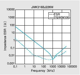
A multilayer ceramic capacitor(it abbreviates to MLCC below) of 22uF/6.3V (Taiyo yuden JMK316BJ226ML) was added at the input of Q6.
[fig.2 Reference The characteristics of JMK316BJ226ML - It reproduced from the data sheet of Taiyo Yuden]
A MLCC of 1u/16V (Murata GRM188F11C105ZA01D) was added at the output of Q6.
EC10 was exchanged to 1500uF/6.3V(Panasonic EEUFK0J152L) and in parallel to it, a MLCC of 22uF/6.3V added.
It added one MLCC of 1u/16V each between pins of AD36(V1.5) and AD34(Vss) of CPU sockets.
EC12 was exchanged to 1500uF/6.3V(Sanyo 6MV1000MG) and in parallel to it, a MLCC of 22uF/6.3V added.
[fig.3 Q6 and EC10 relating circuit]
The instability at the time of high load is canceled now.
Vmem/Vio relating circuit
Q12, Q17: Although AME1084ACDT is weak for capacitive load, a capacitor of rather small ESR
can be used at the each output of the regulators, because its phase margin is increased by
its rather high ratio of output voltage / refference voltage,
and also by the series resistors of R220 and R221 which is used to combine power.
These resistors make slight voltage stability a sacrifice, and make capacitive load stability
increase.
The replacement here is a capacitor of moderate ESR(Z=44mΩ) Panasonic FK and MLCC 100nF/16V in parallel.
Although the limit in a high load test had about 96MHz FSB and no great difference even if it raised
voltage a bit by the standard of 3.35V to 3.45V,
when it is made adventurous off-spec. 3.7V, an error will not be caused by the 100MHz FSB high load test.
[fig.4 Q12/Q17 relating circuit]
XR114 and R117 are changed into 200 ohms, and XR115 and R116 are changed into 390 ohms.
EC27 was exchanged to 1500uF/10V(Rubycon 10MBZ1500M) and in parallel to it, a MLCC of 22uF/6.3V added.
EC28 was exchanged to 1500uF/6.3V(Panasonic EEUFK0J152L) and in parallel to it, a MLCC of 100nF/16V added.
EC31 was exchanged to 1000uF/6.3V(Sanyo 6MV1000WG) and in parallel to it, a MLCC of 22uF/6.3V added.
EC32 was exchanged to 1500uF/6.3V(Panasonic EEUFK0J152L) and in parallel to it, a MLCC of 100nF/16V added.
EC17 was exchanged to 1500uF/6.3V(Panasonic EEUFK0J152L) and in parallel to it, a MLCC of 100nF/16V added.
Since the shortage of a decoupling of 440BX is also serious, although it is a dangerous place, four MLCC(s) of 1u/16V are added on to the power supply via-hole of at the solder side.(fig.5)
[fig.5 440BX decoupling capacitor placement]
The instability at the FSB frequency of 100MHz is canceled now.
V2.5 relating circuit
Q9: AME1085CD was exchanged to LT1585CT(Lenear technology)
EC26 was exchanged to 1500uF/6.3V(Panasonic EEUFK0J152L) and in parallel to it, a MLCC of 22uF/16V added.
EC16 was exchanged to 1000uF/6.3V(Sanyo 6MV1000WG) and in parallel to it, a MLCC of 22uF/6.3V added.
Soothing and the feeling were stabilized by this :-)
Vcore relating circuit
The chemical capacitors at the input of the Vcore regulator are exchanged to 1500u/10V(Rubycon 10MBZ1500M)
and in parallel to it a MLCC of 22uF/6.3V added. Eight places (EC20, EC21, EC24, EC25, EC18, EC19, EC22, and EC23).
The chemical capacitors at the output of the Vcore regulator are exchanged to 1500u/10V(Rubycon 10MBZ1500M)
Six places (EC2, EC13, EC14, EC7, EC8 and EC9).
It added one MLCC of 1u/16V each between Vcore and Vss pins around PLL and Vref pins of CPU sockets. Six places.
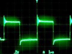
[fig.6 Vcore switch] 2V/div, 1us/div, heavy load
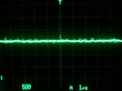
[fig.7 Vtt] 500mV/div, 1us/div, heavy load
Ringing is fairly severe when a FET switch portion is looked at with an oscilloscope.
Although it may be better to put snubber of about 4.7Ω-4.7nF as a dumper since it had a little crosstalk to Vtt,
For the moment, it is likely to be so much uninfluential, leave it as is.
Fan control output
The pulse width modulated output of the fan controller lacks noise suppresser,
which should better be used if you use poor DC fan.
Switching current to an inductive load generates sevier high voltage noise.
A snubber of 100nF to 1uF MLCC with 100Ω in series will be enough.
It added one snubber of MLCC of 1u/16V and 100Ω each between Vfan and GND pins of fan connectors.
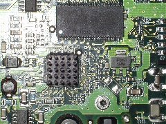
Cooling
In the original state, the heat sink of the North bridge where even thermal joint compound was not applied is exchanged for NB-47J(Zalman) due to a stock available.
The heat sink part of ACK7L for Athlon of Aopen is diverted to the heat sink of the CPU(s), the part was processed, and the fan of 6cm/4800rpm was attached.
Plane polish was given in passing also at the heat spreader of CPU.
Although the effect was not necessarily expected by the reason for saying that it is likely to be in fashion to stick a heat sink on FET of a Vcore regulator recently, it attached :-)
When the temperature in a case goes up, although application is continuing working, a keyboard and a mouse may freeze.
Wondering if it works, when a chip heat sink was attached to W83977EF which gets fairly hot with the heat of a video card,
the problem stopped recurring.
However, since temperature measurement was not necessarily carried out exactly, it is uncertain whether it is that a cause is temperature.
Examination
With 512MB(128MB+128MB+256MB) of memory and two Celeron 366 processors,
stable operation is checked running two processes of Prime95 torture test with following conditions -
FSB=100MHz, Vcore=2.1V, Ta=26 to 29 degrees centigrade.
Continuation load examination time is 16 hours.
System configuration
Operating system : Microsoft Windows 2000 SP4
Power supply : Aopen AO350-12PN
Mother board : Abit BP6 modified (D.U.T.)
BIOS : BP6 RV
CPU
CPU1 : Intel Celeron 366
CPU2 : Intel Celeron 366
Memory
Bank1 : PC133CL3-256MB
Bank2 : PC100CL2-128MB
Bank3 : PC100CL2-128MB
AGP : Nvidia Geforce4 MX440SE
PCI1 : -
PCI2 : Promise FastTrack100 TX2 (Mirror)
IDE1
Master : Maxtor 6Y080P0
Slave : -
IDE2
Master : Maxtor 6Y080P0
Slave : -
PCI3 : Adaptec AUA-3100LP
PCI4 : Corega GEther PCI-T32
PCI5 : -
ISA1 : -
ISA2 : -
FDD : Mitsumi 3.5 inch 2 mode floppy drive
IDE1
Master : Pioneer DVD-120
Slave : -
IDE2 : -
IDE3(HPT366) : -
IDE4(HPT366) : -
A video card Geforce4 FX5200 was also tried, it seems to be OK to the extent that it makes 3D Mark03 run for the time being.
It shows 1054 3DMarks. Since uneasiness is in a power supply related portion, the video card is left MX440SE*2.
if it is MX440SE, 11 3D Marks, too bad.
With the difference of every CPU, the overclocking tolerance of CPU1 seems to be low,
and although the effect was not certain, the weaker one (CPU1) was mounted in the socket from the North bridge.
If it tries on 104MHz operation and high load is continued at high temperature,
Incorrect operation or freeze occur, seemingly whose internal cache of one of the two's CPU caused the error.
Although a floating calculation error is not detected just before freezing, a comparison error occurs in a specific bit in continuation of block move.
Since the error seldom improves even if it raises core voltage to 2.2V, the limit of this CPU seemingly about 550MHz(100MHz FSB by 5.5) or so.
But since some improvement was found by Vcore=2.2V, stable operation was checked at 100MHz FSB,
at temperature 26 to 32 degrees centigrade, by burnP6, Prime95, UD agent and 3DMark03 once again for 26 hours,
and it considered as a common setup.
Postscript
Since it is a maintenance with parts on hand, it cost almost no money but time,
When you buy it ordinarily, for LT1585CT is about 1000 yen, the electritic capacitor of 1000uF/6.3V or so is about 100 yen,
If, and part cost is united minutely, doesn't it become the amount of money to the extent that he can buy it with a mother board of today?
Well, since it is 440BX and is already a hobby, I will consider as good.
Oh, two pieces of ACK7L ...If the same time and effort is applied,
I have felt that it was better to fix Tyan Tiger MP S2460 which the power supply connector was burn.
Note *1: It will be stabilized if EC10 originally 100uF is exchanged for 1500uF, or it is 2200uF and
is conversely unstable, It's O.K. here, N.G. there, the problem of the capacity of the modification part which became
the center of attention about stability of BP6 on the Web site. *2: Since it is a too much bad score when it is MX440SE,
while substituting for Albatron FX5200U later and making the same examination various -- power supply voltage --
since it was likely to be satisfactory when investigating, it exchanged for that.
Addition.
The measure against heat of Maxtor 6Y080P0 (ST L7250E Rev.1.0).
In spite of carrying out compulsion air cooling by two 8cm/2000rpm fans about 80GB of hard disk of Maxtor currently used by mirroring,
while performing the Array synchronization, it may be begun to cause a defect of operation.
Since it seems that the L7250E common name SMOOTH of motor controller chip of ST Microelectronics has caused the defect of operation with heat,
although the chip heat sink was stuck on SMOOTH on the heat conduction adhesion tape of 3M, after a long time, it is separating and does not work by distortion by the heat cycle.

![[Mail]](/~lyuka/images/mail.gif)


 © 2000 Takayuki HOSODA.