Patent
Redundancy and High Reliability
The essence of redundant design is to improve system reliability by reducing the probability of simultaneous failures through duplication of components that exhibit relatively high failure rates. If the cost of redundancy, including operational convenience and maintainability, is lower than the cost associated with failures, adopting redundant systems becomes worthwhile. Furthermore, improving resistance against external disturbances and enhancing abnormality detection capability contributes not only to improved system reliability and prevention of human or material damage, but also to maintaining and improving customer confidence in both the company and its products, ultimately contributing to long-term profitability. From the viewpoint of preventing abnormal shutdowns or unintended control caused by malfunction or failure of the fault detection system itself, it is also important to consider the intrinsic reliability of the abnormality detection system itself.
Example Application
Consider a power motor control system in which four operating states — "forward rotation", "reverse rotation", "braking", and "idle" — are transmitted over a signal cable using a 2-bit control signal. If, during operation, disconnection or short-circuit faults occur in the signal lines, or contact failure arises due to oxidation or sulfurization of the connectors, the motor control state may suddenly change from forward rotation to reverse rotation. Such an event may result in destruction or burnout of the motor itself, as well as damage or accidents involving the equipment driven by the motor. In such applications, it is desirable not only to introduce redundancy into the control signals, but also to perform time-domain filtering and operational state monitoring.
High-Reliability Power Motor Driver Interface
Through many years of development experience in railway control systems and industrial equipment, we have accumulated expertise in high-reliability interface technologies. The following power motor driver interface is one example constructed based on that experience. For abnormality feedback detection, we intentionally employ electric wiring and temperature sensing resistors, which are among the least failure-prone hardware elements available.
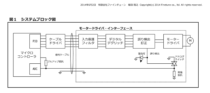
Figure 1 shows the system block diagram.
Equation 1 shows the encoding logic for the control signal.
Equation 1: Encoding logic for conversion of the control signal into a (5,2) Hamming code:c[4..0] = (d1, d0, !d1, d0 $ d1, !d0); System Block Diagram Description
- The internal 2-bit control signal of the microcontroller is encoded into the (5,2) error-correcting code shown in Equation 1 and output from the built-in PIO ports. This code enables single-bit error correction as well as detection of disconnected signal cables and invalid control symbols. Because the encoding is performed internally within the microcontroller, faults in the built-in PIO output pins themselves can also be detected as errors.
- The encoded control signals pass through cable drivers, signal cables, input protection filters, digital deglitch circuits, and error detection/correction logic before becoming the final motor driver control signals.
- Since the control signals are transmitted in parallel, the interface can tolerate low-frequency PWM operation generated by transitions between forward rotation and idle states.
- The temperature at the motor driver's monitored location is detected using temperature sensing resistors, forming monitor signals that are transmitted through signal cables and measured by the microcontroller's built-in ADC.
- Under normal conditions, the ADC-converted monitor signal remains within the range corresponding to the expected temperature range. However, cable disconnection or short-circuit faults result in abnormal values near the maximum or minimum range, allowing abnormal conditions in the monitoring signal path itself to be detected.
- When an error is detected by the error detection/correction logic, an error detection signal is asserted.
- Upon error detection, the motor driver is forced into a predefined safe state.
- Upon error detection, analog switches connected in series or parallel with the temperature sensing resistor are switched accordingly. This allows the microcontroller side to recognize the occurrence of an error as an abnormal ADC value within a predefined range.
- An alarm indicator is activated when an error is detected.
- During abnormal temperature conditions or similar faults, the microcontroller can intentionally output an invalid control symbol that is recognized as an error, forcing the motor driver into a predefined safe state while simultaneously activating the alarm indicator.
Summary
By adding relatively simple and low-cost circuitry implementing the above concepts to conventional motor driver interfaces, it becomes possible to construct safer systems equipped with a robust fault detection scheme capable of handling a wide range of abnormal conditions.
Technology Release
Ten years after patent registration,
this patent is scheduled to transition into a "technology release phase" in August 2026.
This patent is based on the design philosophy that
abnormality detection systems must possess higher reliability and robustness than the drive systems they supervise.
In other words,
safety-related systems should be simpler,
less failure-prone,
and designed such that their failure modes remain predictable.
We hope that both this technology and the fail-safe design philosophy behind it will contribute,
even in a small way,
to future advances in high-reliability motor control and safety-oriented system design.
Technical development, design support, and consulting services related to this technology and its applications remain available. Please feel free to contact us by email.

![[Mail]](/~lyuka/images/mail.gif) © 2000 Takayuki HOSODA.
© 2000 Takayuki HOSODA.