 Japanese edition is here.
Synthesize	: [XEQ] Z→W
Analyze  	: [XEQ] W→Z
Zo→Zdiff		: [XEQ] ZD
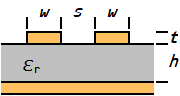
Var "E" : relative permittivity			(W→Z, Z→W)
Var "H" : dielectric height           [mm]	(Zo→Zdiff)
Var "S" : side gap                    [mm]	(Zo→Zdiff)
Var "T" : conductor thickness         [mm]	(W→Z, Z→W)
Var "W" : microstripline width        [mm]	(W→Z)
Var "Z" : charactoristic impedance    [Ω]	(Z→W, Zo→Zdiff)
Var "E" : relative permittivity
Var "H" : dielectric height           [mm]
Var "S" : side gap                    [mm]
Var "T" : conductor thickness         [mm]
Var "P" : work/velocity of propagation
Var "W" : microstripline width        [mm]
Var "Z" : charactoristic impedance    [Ω]
Flag 88 : will be cleared
Var "P" : velocity of propagation
Var "W" : microstripline width        [mm] (Synthesized)
Var "Z" : charactoristic impedance    [Ω] (Analyzed)

Reg t: open end compensation          [mm]
Reg z: rightangle bend compensation
Reg y: velocity of propagation
Reg X: microstrip line width          [mm] (Synthesized)
     | Characteristic impedance       [Ω] (Analyzed)
uZW - Rev 1.8: Jun. 5 2017 - Copyright(c) 1998-2017 Takayuki HOSODA, All rights reserved.
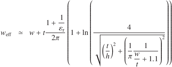
Synthesis Effective width Characteristic impedance Velocity of
propagationOpen-end compensation Rightangle bend
compensationDisplay results Analyze Coefficient Differential
impedance00 { 517-Byte Prgm } 01 LBL "Z→W" 02 MVAR "Z" 03 MVAR "E" 04 MVAR "H" 05 MVAR "T" 06 MVAR "W" 07 VARMENU "Z→W" 08 STOP 09 EXITALL 10 RCL "Z" 11 XEQ C 12 ÷ 13 E↑X 14 1 15 - 16 STO "P" 17 10 18 RCL× "H" 19 0.6 20 RCL+ "E" 21 SQRT 22 RCL× "Z" 23 69 24 ÷ 25 E↑X 26 ÷ 27 STO "W" 28 RCL- "T" 29 CF 88 30 PGMSLV "uX" 31 SOLVE "W" 32 XEQ B 33 RCL "W" 34 RTN",W=" 158 ARCL "W" 159
v=" 160 ARCL "P" 161
- "Z→W"
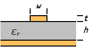
- Synthsize Microstrip line
- "W→Z"
- Analyze Microstrip line
- "μX"
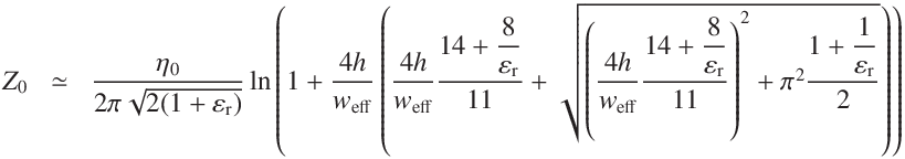
- The sub-routine to calculate the transmission line impedance (error ≤ 2%[1])
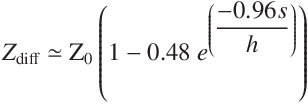
- "ZD"
- Differential impedance of the microstrip line pair[3]
The practical ranges for Zo and Zdiff are from 20Ω to about 150Ω with possible errors of up to ±10%.
- B
- The sub-routine to calculate velocity of propagation, open end compensation and rightangle bend compensation.
(0.25 ≤ W/H≤ 2.75, 2.5 ≤ εr ≤ 25, VSWR ≤ 1.1 [2](i.e. S11 ≤ -26dB))
uZW : 'Z→W uX W→Z' (ustrip-1.8.raw, 520 byte, raw program file for the Free42)
where,
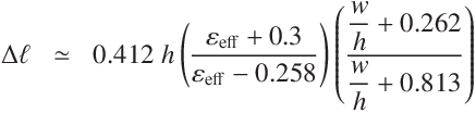
Open end effect length
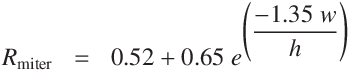
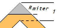
Rightangle bend compensation
Differencial impedance of side coupled microstrip line
Input Output
Reg t : 77.0125481499e-3   [mm]
Reg z : 577.860580911e-3
Reg y : 553.140318922e-3
Reg X : 358.360892363e-3   [mm]
Online calculator - Synthsize/Analyze microstrip transmission line
for the HP 15C - Synthsize/Analyze microstrip transmission line
for the HP 32sII - Synthsize/Analyze microstrip transmission line
Ostrowski's method

![[Mail]](/~lyuka/images/mail.gif) © 2000 Takayuki HOSODA.
Powered by
© 2000 Takayuki HOSODA.
Powered by